SDY160 BUTT FUSION Welding MACHINE OPERATION MANUAL
Special Description
Before operating the machine, anyone should read this description carefully and keep it well to ensure the equipment and operator’s safety, as well as others’ safety.
2.1 The machine is used to weld pipes made from PE, PP, PVDF and can not be used to weld material without description, otherwise the machine may be damaged or some accident may be resulted in.
2.2 Don’t use the machine in a place with potential hazard of explosion
2.3 The machine should be operated by responsible, qualified and trained personnel.
2.4 The machine should be operated on a dry area. The protective measures should be adopted when it is used in rain or on wet ground.
2.5 The machine is operated by 220V±10%, 50 Hz. If extended wire should be used, it should have enough lead section according its length.
2.6 Before using the machine, fill 46# hydraulic oil. Make sure the hydraulic oil is enough for working; the oil level should be 2/3 of the tank. Replace the iron oil tank cap by the red plastic air bleed cap or the pressure can not be hold.
Safety
3.1Take care when operating and transporting the machine according to all the safety rules in this instruction.
3.1.1 Notice when using
l The operator should be responsible and trained personnel.
l Completely inspect and maintain the machine per year for the safety and machine’s reliability.
l Dirty and crowed work site would not only lower working efficiency, but cause accident easily, so it is important to keep work site clean and no other obstacles.
3.1.2 Power
The electricity distribution box should have ground fault interrupter with relevant electricity safety standard. All safety protection devices are indicated by easily understandable words or marks.
Earthing: The whole site should share the same ground wire and the ground connection system should be completed and tested by professional people.
3.1.3 Connection of machine to power
The cable connecting machine to power should be mechanical concussion and chemical corrosion proof. If the extended wire is used, it must have enough lead section according to its length.
3.1.4 Storage of electrical equipment
For the min. dangers, all equipment must be used and stored correctly as follows:
※Avoid using temporary wire not complying with standard
※ Do not touch electrophorus parts
※ Forbid hauling off the cable to disconnect
※ Forbid hauling cables for lifting equipment
※ Do not put heavy or sharp object on the cables, and control the temperature of cable within limiting temperature (70℃)
※ Do not work in the wet environment. Check if the groove and shoes is dry.
※ Do not splash the machine
3.1.5 Check insulation condition of machine periodically
※ Check the insulation of cables specially the points extruded
※ Do not operate the machine under extreme condition.
※ Check if the leakage switch works well at least per week.
※ Check the earthing of the machine by qualified personnel
3.1.6 Clean and check the machine carefully
※Do not use materials (like abrasive, and other solvents) damaging the insulation easily when cleaning the machine.
※ Make sure the power is disconnected when finishing job.
※Make sure there is no any damage in the machine before reusing.
If only following above mentioned, the precaution can work well.
3.1.7 Starting
Make sure the switch of the machine is closed before powering it on.
3.1.8 Untrained person is not allowed to operate the machine anytime.
3.2.Potential Dangers
3.3.1 Butt fusion machine controlled by hydraulic unit:
This machine is only operated by professional person or others with a certificate for operation, otherwise unwanted accident maybe caused.
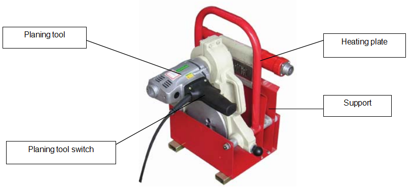
3.3.2 Heating Plate
The max temperature can reach 270℃, so the following things should be noticed:
------Wear safety gloves
-------Never touch the surface of the heating plate
3.3.3 Planing tool
Before shaving the pipes, ends of pipes should be cleaned, especially clean the sand or other draff crowed around the ends. By doing this, the lifetime of edge can be prolonged, and also prevent the shavings are thrown out to danger people.
3.3.4 Basic Frame:
Make sure the pipes or fittings are fixed correctly to get the right alignment. When joining pipes, the operator should keep a certain space to the machine for personnel safety.
Before transporting, make sure all the clamps are fixed well and can not fall down during transportation.
Follow all the safety marks in the machine.
Applicable Range and Technical Parameter
| Type |
SDY160 |
| Materials |
PE,PP,PVDF |
| Max. range of diameter |
160 mm |
| Ambient temp. |
-5~45℃ |
| Power supply |
~220V±10 % |
| Frequency |
50 Hz |
| Total current |
15.7 A |
| Total power |
2.75 kW |
| Include:Heating plate |
1 kW |
| Planing tool motor |
1 kW |
| Hydraulic unit motor |
0.75 kW |
| Dielectric resistance |
>1MΩ |
| Max. Pressure |
6 MPa |
| Total section of cylinders |
4.31cm2 |
| Volume of oil box |
3L |
| Hydraulic oil |
40~50(kinematic viscosity)mm2/s, 40℃) |
| Undesired sound |
80~85 dB |
| Max. Temperature of heating plate |
270℃ |
| Difference in surface temperature of heating plate |
±5℃ |
Descriptions
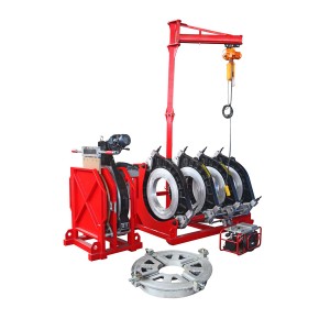
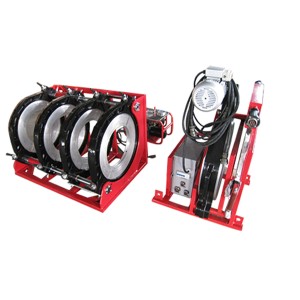
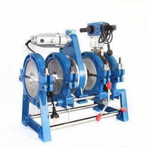
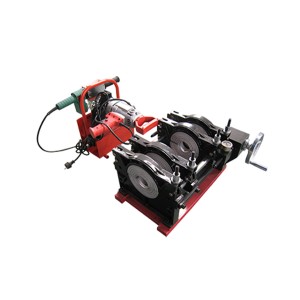
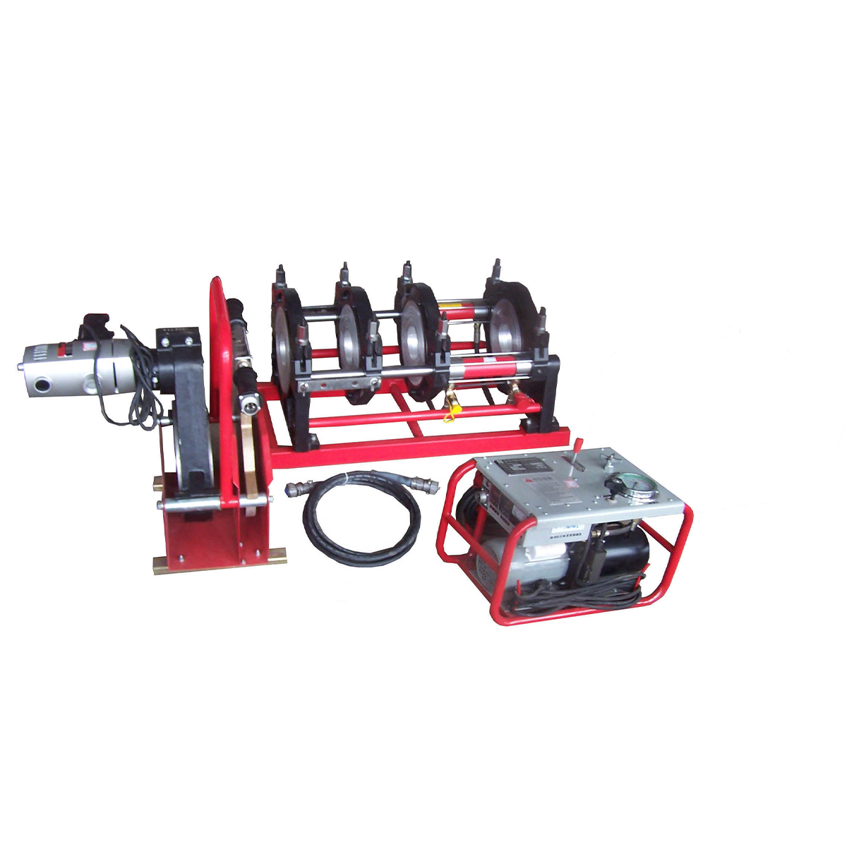
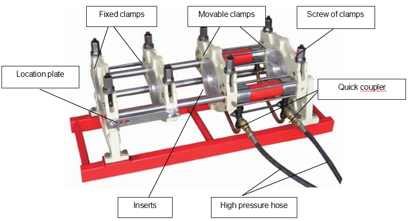
The machine consists of basic frame, hydraulic unit, heating plate, planing tool and support.
5.1 Frame
5.2 Planning tool and heating plate
5.3 Hydraulic unit
Instruction for Use
6.1 The whole equipment should be placed on a stable and dry plane to operate.
6.2 Before operation make sure the following things:
u The machine is in good conditions
u The power complies with the requirements according to the butt fusion machine
u Power line is not broken or worn
u All instruments are normal
u The blades of planning tool are sharp
u All necessary parts and tools are available
6.3 Connection and preparation
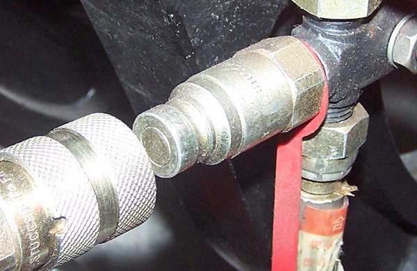
6.3.1 Connect the basic frame to hydraulic unit by quick couplers.
6.3.2 Connect the heating plate line to electric box in hydraulic unit.
6.3.3 Connect the heating plate line to heating plate.
6.3.4 Install appropriate inserts to frame according to the outside diameter of pipes/fittings.
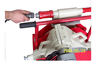
6.3.5 According to the requirements of fitting and welding process, set the temperature in temperature controller and set time in timer. (See section 7 this manual).
6.4 Welding steps
6.4.1 Pipes
Before welding, firstly, check if the material and its pressure grade are the required ones. Secondly check if there are scratches or fissures on the surface of pipes/fittings. If the depth of scratches or fissures exceeds 10% of the wall thickness, cut the section of scratches or fissures. Clean the pipe end’s surfaces with clean cloth to keep the pipe’s ends clean.
6.4.2 Clamping
Place the pipes/fittings in inserts of frame and keep the ends to be welded be the same length (no effect on the planning and heating of the pipe). The pipe out of the basic frame should be supported to the same central axial of clamps. Fasten the screws of clamps to fix the pipes/fittings.
6.4.3 Adjust the pressure
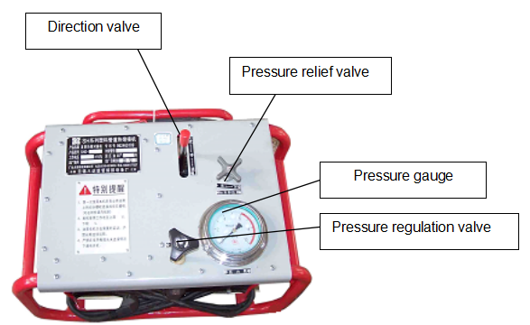
Open fully the pressure regulation valve completely, lock the swing check valve tightly and then push forward the direction valve meanwhile adjust the pressure regulation valve till the cylinder begin to move, at this point the pressure in the system is the drag pressure.
Open the pressure regulation valve completely, lock the swing check valve tightly and then push forward the direction valve meanwhile adjust the pressure regulation valve to set the system pressure equals to drag pressure add butting pressure.
6.4.4 Planing
Open the pipes/fittings ends after turning swing check valve anti-clockwise to the end. Put the planning tool between the pipes/fittings ends and switch it on, close the pipes/fittings ends by acting on the direction valve meanwhile slowly turn swing check valve clockwise until there are continuous shavings appearing on both sides. Turn the swing valve anti clockwise to relief the pressure, in a moment later open the frame, switch off the planing tool and remove it.
Close the pipes/fitting ends and checks the alignment of them. The maximal misalignment should not exceed 10% of the wall thickness, and it could be improved by loosening or tightening the screws of clamps. The gap between two pipe ends should not exceed 10% of wall thickness; otherwise the pipes/fittings should be planed again.
Caution: The shavings thickness should be within 0.2~0.5 mm and it can be adjusted by adjusting the height of the planning tool blades.
6.4.5 Heating
Clear the dust or slit on the surface of heating plate (Caution: Don’t damage PTFE layer on the surface of heating plate.), and make sure the temperature has reached the required one.
Put the heating plate between the pipe ends after it reaches required temperature. Close the pipes/fittings ends by operating direction valve and raise the pressure to specified pressure by swinging pressure regulation valve till the bead reaches specified height.
Turn swing check valve anti-clockwise to reduce the pressure (not more than drag pressure) and turn swing check valve in clockwise direction to the end.
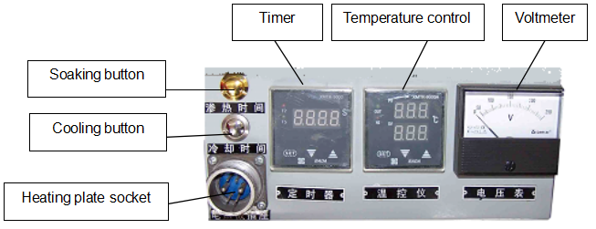
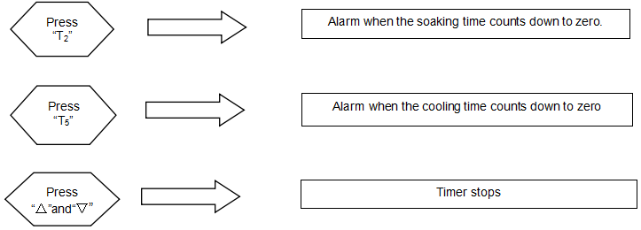
Press the button “T2” , the soaking time begins to count and the time will count down to zero by second, then the buzzer will buzz(see section 7)
6.4.6 Joining and cooling
Open the frame and take out the heating plate and close two melting ends as quickly as possible.
Keep the bar of direction valve on the close position for 2~3 minutes, put the bar of direction valve on middle position and press the button (“T5”) to count cooling time until it is over. At this point, the machine will give an alarm again. Relief the pressure, loose the screw of clamps and then take out the jointed pipes.
Timer and Temperature Controller
If one of the parameters is changed, such as outside diameter, SDR or material of pipes, the soaking time and cooling time should be reset according to the welding standard.
7.1 Timer setting
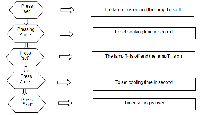
7.2 Instruction for Use
7.3 Temperature controller setting
1) Press “SET” for more than 3 seconds till “sd” is shown in the upper window
2) Press “∧” or “∨” to change the value to specified (press“∧” or “∨” continuously, the value will plus or minus automatically )
3) After setting, press “SET” to go back to monitoring and controlling interface
Reference of Welding Standard(DVS2207-1-1995)
8.1 Because of difference in welding standard and PE material, the time and pressure vary in different phases of welding. It suggests that the actual welding parameters should be offered by pipes and fittings’ manufacturers.
8.2 Given welding temperature of pipes made from PE、PP and PVDF by DVS standard ranges from180℃ to 270℃. Application temperature of heating plate is within 180~230℃, and its max. surface temperature can reach 270℃.
8.3 Reference standard DVS2207-1-1995

|
Wall thickness (mm) |
Bead height(mm) |
Bead build-up pressure(MPa) |
Soaking time t2(sec) |
Soaking pressure (MPa) |
Change-over time t3(sec) |
Pressure build -up time t4(sec) |
Welding pressure(MPa) |
Cooling time t5(min) |
|
0~4.5 |
0.5 |
0.15 |
45 |
≤0.02 |
5 |
5 |
0.15±0.01 |
6 |
|
4.5~7 |
1.0 |
0.15 |
45~70 |
≤0.02 |
5~6 |
5~6 |
0.15±0.01 |
6~10 |
|
7~12 |
1.5 |
0.15 |
70~120 |
≤0.02 |
6~8 |
6~8 |
0.15±0.01 |
10~16 |
|
12~19 |
2.0 |
0.15 |
120~190 |
≤0.02 |
8~10 |
8~11 |
0.15±0.01 |
16~24 |
|
19~26 |
2.5 |
0.15 |
190~260 |
≤0.02 |
10~12 |
11~14 |
0.15±0.01 |
24~32 |
|
26~37 |
3.0 |
0.15 |
260~370 |
≤0.02 |
12~16 |
14~19 |
0.15±0.01 |
32~45 |
|
37~50 |
3.5 |
0.15 |
370~500 |
≤0.02 |
16~20 |
19~25 |
0.15±0.01 |
45~60 |
|
50~70 |
4.0 |
0.15 |
500~700 |
≤0.02 |
20~25 |
25~35 |
0.15±0.01 |
60~80 |
Remark:Bead build-up pressure and welding pressure in the form is the recommended interface pressure, the gauge pressure should be calculated with the following formula.
Expressions:

Malfunctions Analyses and Solutions
| u Visually check:round bead, good joint |  |
| u Narrow and fall bead. Too high pressure while welding |  |
| u Too small bead. Pressure is not enough while welding |  |
| ◆ There is a ditch between the welding surfaces. Temperature is not enough or change-over time is too long while welding. |
|
| ◆ High & low bead. Different heating time or fusion temperature causes that. |  |
| ◆ Misalignment. Welding under the condition that the misalignment exceeds 10% of pipe wall thickness while align the two ends. |  |

9.2 Maintenance and inspection periods
9.2.1 Maintenance
※ Heating plate coating
Please take care on handling the heating plate. Keep a certain distance away from heating plate. Cleaning of its surface must be done with surface still warm by using a soft cloth or paper, avoid abrasive materials in that might damage the coating.
At regular intervals check as follows
1) Clean the surface by using a quick evaporation detergent (alcohol)
2) Check the tightening of the screws and the cable and plug condition
3) Verify its surface temperature by using infrared-ray scanning
※ Planing tool
It is strongly suggested to keep always clean the blades and wash the pulleys by using a detergent. At regular intervals, carry out a complete cleaning operation.
l Hydraulic unit
Maintain it as follows
n Check periodically the oil level
n Replace totally the oil every 6 months
3) Keep tank and oil circuit clean
9.2.2 Maintenance & Inspection
Ordinary inspection
|
Item |
Description |
Inspect before use |
First month |
Every 6 months |
Every year |
|
Planning tool |
Mill or replace the blade
Replace the cable if it is broken Retighten mechanical connections |
● ● |
● |
|
● ●
|
|
Heating plate |
Rejoined the cable and socket
Clean surface of heating plate, recoat PTFE layer again if necessary Retighten mechanical connections |
● ●
● |
● |
|
●
|
|
Temp. control system |
Checkout the temperature indicator
Replace the cable if it is broken |
● |
|
|
● ● |
|
Hydraulic system |
Checkout pressure gauge
Replace seals if the hydraulic unit is leak Clean the filter Make sure the oil is enough for operation Change the hydraulic oil Replace if the oil hose is breakage |
● ● ● |
|
● |
● ●
● ●
|
|
Basic Frame |
Retighten screws in the end of frame axis
Spray antirust paint again if necessary |
●
|
●
|
●
|
● |
|
Power Supply |
Press the testing button of circuit protector to make sure it can working normally
Replace the cable if it is broken |
●
● |
|
● |
|
“●”………… maintenance period
9.3 Frequent malfunction analyses and solutions
During the using, hydraulic unit and electrical units may appear some problems. Frequent malfunction is listed as follows:
Please use tools attached, spare parts or other tools with a safety certificate while maintain or replace parts. Tools and spare parts without safety certificate are forbidden to be used.
|
Malfunctions of hydraulic unit |
|||
|
No |
malfunction |
malfunction analyzes |
Solutions |
|
1 |
The pump motor does not work |
|
|
|
2 |
The pump motor rotate too slowly with abnormality noise |
|
1. Make sure the motor load is less that 3 MPa
2. Repair or replace the pump 3. Clean the filter 4. Check the instability of power |
|
3 |
The cylinder works abnormally |
|
u Replace the direction valve.
u Move the cylinder several times to outgo the air. u Adjust the system pressure u Replace the quick coupler u Lock the valve |
|
4 |
Cylinder leak |
1. The oil ring is fault
2. The cylinder or piston is damaged badly |
1. Replace the oil ring
2. Replace the cylinder |
|
5 |
The pressure can not be increased or the fluctuation is too big |
1. The core of overflow valve is blocked.
2. The pump is leak. 3. The joint slack of pump is loosened or key groove is skid. 4. The pressure relief valve is not locked |
1. Clean or replace the core of over-flow valve
2. Replace the pump 3. Replace the joint slack 4. Lock the valve |
|
Malfunctions of electrical units |
|||
|
1 |
The machine does not work |
|
1. Check the power cable
2. Check the working power 3. Open the ground fault interrupter |
|
2 |
Ground fault switch trips |
|
1. Check the power cables
2. Check the electrical elements. 3. Check the higher-up power safety device |
|
3 |
Abnormal temperature increasing |
1. The temperature controller switch is open
2. The sensor (pt100)is abnormal. The resistance value of4 and 5 of heating plate socket should be within 100~183Ω 3. The heating stick inside heating plate is abnormal. The resistances between 2and 3 should be within23Ω. Insulation resistance between head of heating stick and outside shell must be more than 1MΩ 4. Should the temperature controller readings be more than 300℃, which suggest he sensor may be damaged or the connection is loosen. Should the temperature controller indicate LL, which suggests the sensor have a short circuit. Should the temperature controller indicate HH, which suggests the circuit of sensor is open. 5. Correct the temperature by button located on the temperature controller.
|
1. Check the connection of contactors
2. Replace the sensor
3. Replace the heating plate
4. Replace the temperature controller
5. Refer to the methods to set the temperature 6. Check and replace the contactors if necessary |
|
4 |
Lose of control when heating |
The red light is shine, but the temperature still goes up, that is because the connector is fault or the joints 7 and 8 can not open when get the required temperature. |
Replace the temperature controller
|
|
5 |
Planing tool does not rotate |
The limit switch is ineffective or the mechanical parts of planing tool are clipped. | Replace the planning tool limit switch or minor sprocket |
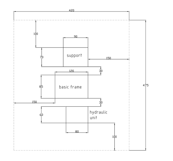
Space Occupation Chart
Wuxi Shengda Sulong Technology Co., Ltd
Tel: 86-510-85106386
Fax: 86-510-85119101
E-mail:shengdasulong@sina.com